This guide details the exact symptoms, diagnostic steps, root causes, and repair options for a failed stepper motor driver, commonly found in 3D printers, CNC machines, and industrial automation. You will learn how to pinpoint the failure, whether it’s the driver chip, a power component, or a connection issue, and decide between DIY repair and professional service.
What’s Happening — Symptoms in Detail
Your industrial motor just stopped moving, or it’s behaving erratically. Here’s exactly what you might be experiencing:
Symptom 1: Complete Motor Stoppage
- The motor is locked in place and will not move at all.
- No sound comes from the motor when you send a movement command.
- The motor might feel stiff or ‘cogged’ when you try to turn it by hand.
- This often happens on startup or mid-operation after a power surge or short circuit.
Symptom 2: Motor Vibrates but Doesn’t Rotate
- The motor hums, buzzes, or vibrates intensely but doesn’t turn.
- You might see the shaft trying to move but it’s stuck, making a high-pitched whine.
- This is a classic sign of a missing phase or a damaged driver output.
- It occurs when a movement command is sent and can happen suddenly.
Symptom 3: Motor Runs Hot or Makes Grinding Noises
- The motor gets extremely hot to the touch within minutes of operation.
- You hear a rough, grinding sound as it moves, especially at low speeds.
- The movement might be jerky or skip steps, causing positional errors.
- This gets worse over time as the driver chip degrades from thermal stress.
Symptom 4: Erratic or Random Movement
- The motor moves on its own, without a command, or twitches randomly.
- It responds to commands but overshoots or moves in the wrong direction.
- This often happens after a firmware update or a crash that caused a power spike.
- The behavior is unpredictable and may come and go.
Symptom 5: Error Codes or No Response
- Your controller screen shows error codes like “Motor Driver Fault”, “Overcurrent”, or “Thermal Shutdown”.
- The driver LED indicator is off, solid red, or flashing a specific pattern.
- The motor is completely unresponsive, even though other electronics work.
- This is a sudden failure most often caused by a shorted motor winding or a power supply spike.
How to Diagnose the Problem Step by Step
Follow these steps in order. You will need a multimeter and a small flathead screwdriver.
Visual Inspection
- Disconnect power. Remove the stepper motor driver board from your machine.
- Normal: The board is clean, no burn marks, and all components are intact.
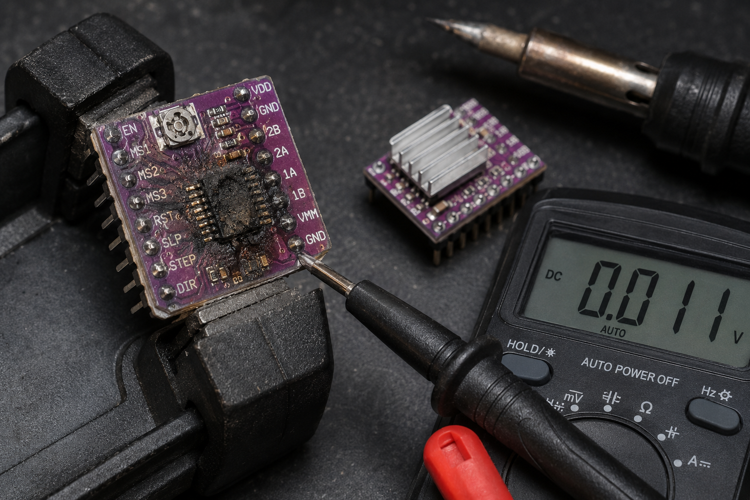
- Abnormal: You see a blackened or scorched area, a cracked chip, or a bulging capacitor. Look for the A4988, DRV8825, TMC2209, or similar driver chip. A visible burn means the driver is dead.
Power Supply Check
- Set your multimeter to DC voltage (20V range).
- Connect the black probe to a ground pin (GND) and the red probe to the power input pin (Vmot or VM).
- Normal: You read the expected voltage (e.g., 12V, 24V).
- Abnormal: Voltage is 0V (no power) or unstable (fluctuating more than 0.5V). This indicates a power supply problem, not a driver problem.
Enable Pin Check
- With power on, measure the voltage on the ENABLE pin (often labeled EN or ENABLE).
- Normal: The pin is LOW (0V) when the motor should be active.
- Abnormal: The pin is HIGH (5V or 3.3V), which disables the driver. This is a firmware or controller board issue.
Output Phase Test (Advanced)
- Disconnect the motor from the driver.
- Set your multimeter to resistance (ohms, 200 ohms range).
- Measure resistance between 1A and 1B pins (coil A). Then between 2A and 2B pins (coil B).
- Normal: Both readings are the same, typically between 1 ohm and 10 ohms (depending on your motor).
- Abnormal: One reading is infinite (open circuit) or zero (short circuit). This means the driver output transistors are blown.
Logic Voltage Check
- Measure voltage on the VDD or VIO pin (logic power).
- Normal: 3.3V or 5V, stable.
- Abnormal: 0V or unstable. The microcontroller cannot talk to the driver.
Step/Direction Signal Test (Oscilloscope Needed)
- Connect an oscilloscope probe to the STEP pin.
- Send a movement command from your controller.
- Normal: You see a clean square wave (pulses) at the expected frequency.
- Abnormal: No pulses, or pulses are very low voltage (<2V). The controller is not sending commands.
Quick Check for Beginners: Perform steps 1, 2, and 4. If you see burn marks, zero voltage, or mismatched resistance, the driver is likely dead.
Detailed Check for Advanced Users: Perform all 6 steps. This will pinpoint if the failure is in the driver chip, power supply, or controller logic.
Why This Happens — Root Cause
The stepper motor driver fails due to specific, avoidable stresses. Here is the engineering behind each common failure:
1. Overcurrent and Short Circuit
- The driver chip (e.g., A4988, DRV8825, TMC2209) has a maximum current rating, typically 1A to 2.5A per phase.
- When a motor winding shorts to ground or another phase, the current spikes instantly.
- The driver’s internal H-bridge transistors (MOSFETs) can’t handle the surge and short out.
- This is accelerated by moisture or conductive dust bridging the motor connector pins.
2. Thermal Overload
- Driving the motor at maximum current for long periods generates heat in the driver chip.
- Without adequate heatsinking or airflow, the internal temperature exceeds the 150°C maximum junction temperature.
- The chip’s thermal protection may shut it down temporarily, but repeated thermal cycles cause bond wire fatigue and eventual failure.
- This is common in enclosed machines with poor ventilation or when the driver is set to 100% current.
3. Power Supply Transients
- Industrial environments have fluctuating power. A spike from a nearby motor start or a lightning strike can exceed the driver’s 35V absolute maximum.
- The driver’s input capacitor (often a 100µF electrolytic) can bulge or leak, no longer filtering the voltage.
- The voltage regulator (if present) fails, sending 24V to the 5V logic pins, instantly killing the chip.
4. Mechanical Crash Force
- When a CNC router or 3D printer crashes into a limit stop, the motor is forced to hold position against a massive load.
- The back-EMF generated by the motor can exceed the driver’s voltage rating, causing a shock to the H-bridge.
- This is a sudden failure that often happens during a crash or immediately after.
5. Electrostatic Discharge (ESD)
- Touching the driver board without grounding can discharge static electricity through the sensitive logic pins.
- The CMOS inputs on the driver chip can be damaged by a voltage as low as 100V.
- This causes intermittent or permanent logic failure, often misdiagnosed as a firmware issue.
Known Issues by Model:
- A4988: Prone to overcurrent failure when used above 1A without heatsink.
- DRV8825: Known for thermal shutdown issues in enclosed spaces.
- TMC2209: More robust but can fail from power supply spikes due to sensitive logic levels.
Can You Fix It Yourself?
Difficulty Level: 3 out of 5 (Moderate)
- Requires basic soldering skills and ability to identify components.
Time Required: 30 to 60 minutes
- 10 minutes for diagnosis
- 20 minutes for replacement (if you have the right part)
- 10 minutes for testing
Skill Level Needed:
- Must have: Ability to use a multimeter, basic soldering (if replacing a surface-mount chip).
- Nice to have: Experience with stepper motor wiring and understanding of datasheets.
Risks:
- Soldering damage: Overheating the board can lift traces or damage nearby components.
- Wrong part: Installing a driver with different current rating can burn the new part or damage the motor.
- Static discharge: Touching the new driver without ESD protection can kill it instantly.
- Power reversal: Connecting the power supply backward will destroy the new driver and possibly the controller.
Tools Required:
- Multimeter (digital, with continuity and voltage modes)
- Soldering iron (temperature-controlled, 350°C)
- Solder (lead-free, 0.8mm diameter)
- Flux (to improve solder flow)
- Desoldering braid or solder sucker
- Small flathead screwdriver (for connectors)
- ESD wrist strap (highly recommended)
- Heat sink compound (if using a separate heatsink)
- Replacement driver module (see cost section)
Cost Breakdown — DIY vs Professional
DIY Cost:
Part #1: 6 Pack Mini L298N DC Motor Driver, MX… — $4.20
- This is a dual H-bridge module, suitable for bipolar stepper motors up to 2A per channel.
- You get 6 modules, so cost per repair is $0.70 if you have a spare.
- Note: The L298N is a classic driver but has higher voltage drop (2V per transistor) than modern chips. It will run hotter.
Part #2: L298N Stepper Motor Driver Controller… — $3.51
- Single module, same L298N chip. Good for one-off repairs.
- Includes a heatsink, which is essential for continuous use.
- Cost: $3.51 plus shipping.
Part #3: 42 Stepper Motor Driver Expansion Boa… — $3.35
- This is an expansion board for a 42mm stepper motor, likely using a TMC2209 or A4988 chip.
- It’s a direct replacement for many 3D printer and CNC drivers.
- Cost: $3.35 plus shipping.
Total DIY Cost: $3.35 to $4.20 (plus $2-$5 shipping)
Professional Repair Cost:
- Diagnostic fee: $50 to $100 (some shops waive this if you proceed with repair)
- Labor: $75 to $150 per hour (typical repair takes 1-2 hours)
- Parts: $5 to $20 (marked up from the $3.35 part)
- Total estimate: $130 to $270
When to Skip DIY:
- If you have no soldering experience or lack a multimeter.
- If the driver is surface-mount (e.g., QFN package) and you don’t have a hot air station.
- If the failure also damaged the controller board (e.g., blown traces). In that case, replace the entire controller.
- If your machine is under warranty, professional repair may be free.
Repair Process Overview
Disconnect Power and Remove the Board
- Unplug the machine and remove the driver board from its socket or mounting.
- Label all wires (1A, 1B, 2A, 2B, GND, Vmot, etc.) with masking tape and a marker.
Identify the Failed Component
- Use your multimeter to confirm the fault (step 4 from diagnosis).
- If the driver chip is burned, proceed to replace it. If a capacitor is bulging, replace that too.
Desolder the Old Driver Chip (if replacing chip)
- Apply flux around the chip’s pins.
- Use desoldering braid to remove as much solder as possible.
- Gently lift the chip with tweezers. If it’s a surface-mount chip, use a hot air station at 350°C.
- Clean the pads with isopropyl alcohol.
Install the New Driver Module
- If using a replacement module (like Part #3), simply plug it into the socket or solder the header pins.
- Ensure the orientation matches (look for pin 1 indicator).
- Solder the pins carefully, avoiding bridges.
Check Power and Ground
- Before connecting the motor, measure resistance between Vmot and GND. It should be >1k ohm (not shorted).
- Apply power and confirm voltage at Vmot and VDD.
Connect the Motor
- Reconnect the motor wires according to your labels. Double-check the coil pairs (1A/1B and 2A/2B).
- Common mistake: Swapping the two coils will cause the motor to vibrate instead of rotate.
Set the Current Limit
- Most drivers have a potentiometer to adjust current. Use a small screwdriver.
- Measure the voltage on the REF pin and calculate: Current = Vref / (8 * Rsense).
- Set it to 80% of the motor’s rated current to avoid overheating.
Test Without Load
- Send a slow movement command (e.g., 10mm at 10mm/min).
- The motor should rotate smoothly without noise.
- If it vibrates, swap one coil’s wires (e.g., swap 1A and 1B).
After the Repair — Testing & Verification
Immediate Verification:
- The motor moves smoothly through its full range without skipping steps.
- The driver chip is warm to the touch but not hot (under 60°C).
- No error codes appear on the controller screen.
First Hour of Use:
- Run a homing sequence or a simple back-and-forth motion at moderate speed.
- Listen for grinding or clicking sounds. If present, the current may be too low or the motor is damaged.
- Check the driver temperature again. If it exceeds 80°C, reduce the current limit or add a heatsink.
First Few Hours:
- Perform a full machine cycle (e.g., print a small part, cut a test piece).
- Monitor for positional drift (the motor loses steps). If it drifts, increase current or acceleration.
- Watch for intermittent failures (random stops). This could indicate a loose connection or a failing power supply.
Long-Term Watch:
- If the driver fails again within a week, the root cause is likely elsewhere (power supply, motor short, or controller logic).
- Consider upgrading to a TMC2209 or TMC5160 for better thermal and overcurrent protection.
Parts You’ll Need
Here are the parts that match this repair. Click the link to check the current price on AliExpress.
| Product | Price |
|---|---|
| 6 Pack Mini L298N DC Motor Driver, MX… | $4.20 |
| L298N Stepper Motor Driver Controller… | $3.51 |
| 42 Stepper Motor Driver Expansion Boa… | $3.35 |
Prices and availability are subject to change on AliExpress.