Your stepper motor driver has failed, causing erratic movement, loud noises, or complete motor shutdown. This guide walks you through exact symptoms, step-by-step diagnosis, root causes, and repair options to get your industrial motor running again.
What’s Happening — Symptoms in Detail
Your stepper motor driver is likely dead or failing. Here’s exactly what you’ll experience:
- Erratic Movement: The motor jumps, stutters, or moves in random steps instead of smooth, precise motion. Some users report the motor ‘jittering’ at low speeds.
- Loud Noises: A high-pitched whine, grinding, or clicking sound from the driver or motor. Normal operation is nearly silent.
- Complete Shutdown: The motor stops moving entirely, even though the controller sends commands. The driver’s LED (if present) may be off or flashing an error code.
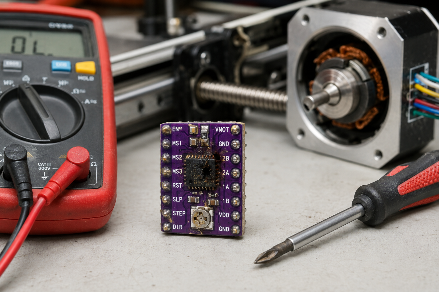
- Overheating: The driver chip (usually a black rectangular IC) gets too hot to touch within seconds of power-on. Normal temperature is warm but comfortable.
- Error Codes on Display: On CNC or 3D printer controllers, you might see ‘M999’ (firmware crash), ‘TMC connection error’, or ‘Driver fault’ on the screen.
When does it happen?
- On startup: The motor refuses to move at all, or makes a grinding noise immediately.
- During use: The motor suddenly loses torque mid-operation, then stops. This often happens after a crash or jam.
- After firmware update: The driver may be misconfigured, causing microstepping or current settings to be wrong.
- Progressive failure: The motor runs fine initially, then gradually loses steps over hours or days. This points to thermal damage.
How does it progress?
- Sudden failure: The driver chip shorts internally, causing immediate shutdown. This is common after a motor stall or power surge.
- Gradual degradation: The driver works but with increasing noise and vibration. The motor may run hot. This indicates failing capacitors or worn-out transistors.
How to Diagnose the Problem Step by Step
Tools needed: Multimeter (set to DC voltage and resistance), small flathead screwdriver, thermal camera or your finger (carefully), a known-good stepper motor (optional).
Power Check: Measure voltage at the driver’s power input terminals. Normal: 12V to 48V DC, steady within 0.5V. Abnormal: Voltage is 0V (blown fuse or power supply issue) or fluctuating more than 1V (bad capacitor or power supply).
LED Status Check: Look for a status LED on the driver board. Normal: Steady green or blue light when powered. Abnormal: No light (dead driver), red light (fault), or flashing pattern (refer to driver datasheet for error codes).
Motor Connection Test: Disconnect the motor from the driver. Measure resistance between each motor wire pair (A+ to A-, B+ to B-). Normal: Resistance between 1 ohm and 10 ohms, consistent across both coils. Abnormal: Open circuit (infinite resistance) or short circuit (0 ohms) — this indicates a bad motor, not the driver.
Signal Input Test: With the driver powered and motor disconnected, use your multimeter to measure voltage at the STEP and DIR input pins while sending a movement command. Normal: You see a 0-5V or 0-3.3V square wave on STEP, and a steady high or low on DIR. Abnormal: No voltage change (controller not sending signals, or broken input circuit on driver).
Temperature Test: Run the motor at low speed for 1 minute. Touch the driver chip (the largest IC). Normal: Warm but you can keep your finger on it for 10 seconds. Abnormal: Too hot to touch immediately — chip is shorted internally.
Advanced Test: Swap the driver with a known-good unit (e.g., from another axis). If the problem moves with the driver, the driver is bad. If not, the issue is elsewhere (motor, wiring, controller).
Why This Happens — Root Cause
Why does a stepper motor driver fail? The driver is a precision electronic component that converts low-power control signals into high-current pulses for the motor. Failures happen due to:
- Overcurrent: The most common cause. When the motor stalls or jams, current surges through the driver’s output transistors (MOSFETs or Darlington pairs). This exceeds their rated limit, causing thermal breakdown. The chip’s internal junctions melt, creating a short or open circuit.
- Overheating: Continuous operation at high current without adequate heatsinking degrades the driver’s silicon over time. The thermal resistance of the package (e.g., TO-220 or QFN) causes localized hot spots. This accelerates electromigration, where metal atoms shift and create voids or shorts.
- Voltage Spikes: Inductive kickback from the motor when it decelerates quickly can generate voltage spikes above the driver’s rating (often 40V or 60V). Without proper snubber circuits or flyback diodes, these spikes punch through the gate oxide of the MOSFETs.
- Poor Power Supply: A noisy or unstable power supply (e.g., from a cheap switching supply) can cause the driver’s internal logic to glitch. This leads to incorrect step timing, missing steps, or latch-up (a condition where the chip locks into a high-current state).
- Physical Damage: Dust, metal shavings, or moisture on the driver board can create conductive paths between pins. This is common in industrial environments. A crash that bends the motor shaft can also transmit vibration to the driver, cracking solder joints.
- Specific Models and Issues:
- A4988: Known for overheating at currents above 1A without heatsinks. The potentiometer for current limit is fragile and can drift.
- DRV8825: Susceptible to voltage spikes from long motor cables. The ’nFAULT’ pin can indicate overcurrent or thermal shutdown.
- TMC2209: Silent operation but sensitive to 5V logic voltage. A 3.3V controller can cause erratic behavior.
- L298N: Older dual H-bridge design. Prone to thermal shutdown and ‘shoot-through’ (both transistors on at once) if the enable pins are not properly controlled.
Can You Fix It Yourself?
Difficulty: 3 out of 5 (Moderate)
- Why: Requires basic soldering skills for driver replacement, or simple screwdriver work for swap-in modules.
Time Required: 30 to 90 minutes
- 30 minutes: If you have a plug-in driver module (e.g., A4988, TMC2209) and just swap it.
- 90 minutes: If you need to desolder a surface-mount driver chip from a custom board.
Skill Level Needed:
- Beginner: Can replace a modular driver (screw terminals, no soldering).
- Intermediate: Can solder through-hole components (e.g., L298N module replacement).
- Advanced: Can desolder and replace a QFN or TSSOP package with a hot air station.
Risks:
- Short Circuit: Incorrect wiring of the new driver can blow it instantly. Double-check polarity and motor coil connections.
- Wrong Current Setting: Setting the current limit too high will overheat the new driver. Too low causes missed steps.
- ESD Damage: Touching the driver pins without grounding can kill the chip before it’s installed.
Tools Required:
- Multimeter
- Screwdriver set (small Phillips and flathead)
- Soldering iron (if replacing soldered components)
- Solder wick or desoldering pump
- Thermal paste (if heatsink is required)
- Tweezers (for small components)
Cost Breakdown — DIY vs Professional
DIY Cost:
- Part #1: 6 Pack Mini L298N DC Motor Driver, MX… — $4.20. These are basic dual H-bridge modules. Good for simple on/off control, but not ideal for microstepping or precision.
- Part #2: L298N Stepper Motor Driver Controller… — $3.51. A classic module for bipolar stepper motors. Requires external current sensing and is bulky.
- Part #3: 42 Stepper Motor Driver Expansion Boa… — $3.35. Likely a breakout board for a specific driver chip (e.g., A4988 or DRV8825). Check chip markings.
- Other costs: Shipping ($5-$10), thermal paste ($3), solder ($2).
Professional Repair Cost:
- Diagnostic fee: $50-$100 (often waived if you proceed with repair).
- Driver replacement: $100-$200 for labor plus $20-$50 for the part.
- Total: $150-$350.
When to skip DIY:
- If the driver is part of a complex control board (e.g., CNC controller with multiple layers) and you lack SMD rework skills.
- If the motor itself is damaged (shorted coil) — replacing the driver will just blow it again. Test the motor first.
- If you need the machine running urgently — professional repair is faster than waiting for parts.
Repair Process Overview
Major Steps:
Power Down and Disconnect: Unplug the machine from power. Wait 5 minutes for capacitors to discharge. Use a multimeter to confirm zero voltage at the driver’s power terminals.
Identify the Driver: Note the exact model number (e.g., A4988, DRV8825, TMC2209). Take a photo of wiring for reference.
Remove the Old Driver:
- For modular drivers: Unplug or unscrew from the main board.
- For soldered drivers: Desolder each pin with a soldering iron and solder wick, or use a hot air station at 350°C.
Prepare the New Driver:
- Set the current limit using the onboard potentiometer (refer to datasheet for voltage formula).
- Apply thermal paste if a heatsink is required.
- Double-check pinout matches the old driver.
Install the New Driver:
- Solder or plug in the new driver, ensuring no solder bridges between pins.
- Reconnect power, motor, and control wires exactly as before.
Configure Firmware (if needed):
- On 3D printers or CNC, update the current, microstepping, and direction settings in the controller firmware (e.g., Marlin, GRBL).
- Enable stealthChop or spreadCycle for TMC drivers as needed.
Common Mistakes:
- Wrong current limit: Measure Vref before powering on. For A4988, Vref = current * 8 * sense resistor value.
- Reversed motor wires: Swapping A+ and A- will cause the motor to vibrate instead of rotating.
- Missing heatsink: Many drivers need active cooling (fan or heatsink) at currents above 1A. Without it, the new driver will fail again.
- Not checking motor: A shorted motor coil will destroy the new driver immediately. Always test motor resistance first.
After the Repair — Testing & Verification
How to know the repair worked:
- Power on test: The driver’s LED lights up steady. The motor holds position without humming.
- Jog test: Send a small movement command (e.g., 1mm on a CNC, 10 steps on a printer). The motor moves smoothly and stops precisely.
- Temperature check: After 5 minutes of continuous low-speed operation, the driver chip is warm but not hot (under 60°C).
- No error codes: The controller reports no faults.
What to watch for in the first few hours:
- Intermittent stuttering: If the motor occasionally skips steps, the current limit may be too low. Increase Vref by 0.05V increments.
- Overheating: If the driver gets hot within 1 minute, reduce current or add a heatsink/fan.
- Burning smell: Immediately power off. This indicates a short or wrong wiring. Check for solder bridges or pinched wires.
- Strange noises: A whine or buzz suggests the microstepping setting is wrong or the driver is in the wrong mode (e.g., spreadCycle instead of stealthChop). Adjust in firmware.
Parts You’ll Need
Here are the parts that match this repair. Click the link to check the current price on AliExpress.
| Product | Price |
|---|---|
| 6 Pack Mini L298N DC Motor Driver, MX… | $4.20 |
| L298N Stepper Motor Driver Controller… | $3.51 |
| 42 Stepper Motor Driver Expansion Boa… | $3.35 |
Prices and availability are subject to change on AliExpress.